


Widely available for many different applications, universal catalytic converters are a popular, economical option. Installing a universal-fit catalytic converter requires a few important steps to ensure the new converter provides maximum efficiency and reliability. Whether you’re installing an EPA or a CARB universal catalytic converter, follow these steps for a successful repair.
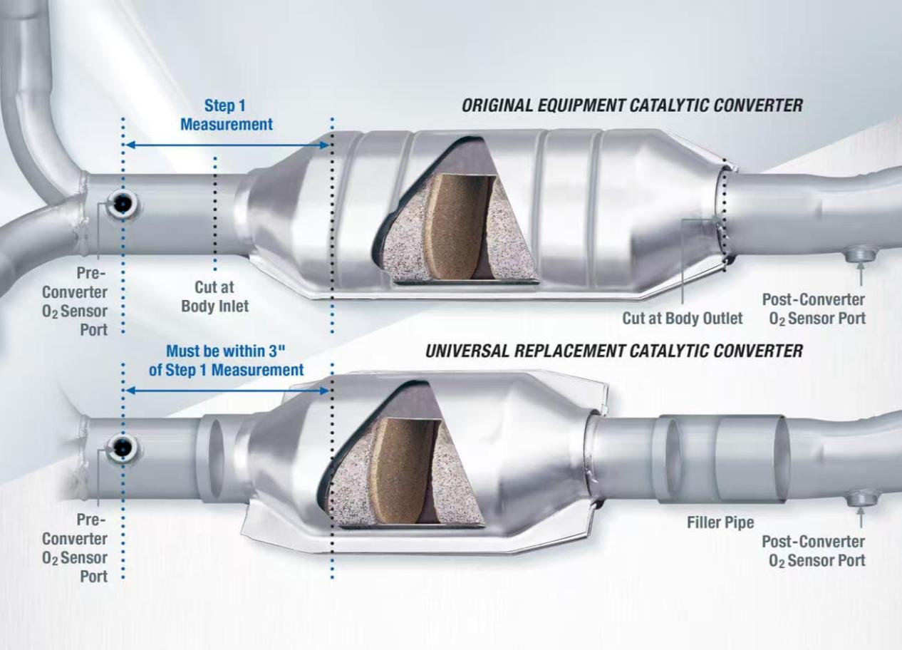

Measure the distance between the front oxygen sensor and the front face of the existing converter. Document this measurement as you’ll need it to position the replacement converter correctly into the system. You will need to keep as close to this measurement as possible with your replacement to ensure light-off and proper function of the replacement converter.

To remove the original converter, make clean cuts at the weld seams (or body inlet and outlet), to the upstream and downstream exhaust pipe between the converter and oxygen sensor(s). The oxygen sensor(s) should remain in the existing location(s). Also, be sure to keep all hangers in the same location(s) – don’t eliminate any.

Slip the replacement universal converter’s inlet and outlet pipes over the vehicle’s corresponding exhaust pipes. CAUTION: Don’t allow the exhaust pipe to contact the converter’s internal ceramic substrate, as this will damage the converter and adversely affect its performance. Make sure the converter’s external emboss markings are facing the ground, with the directional arrow facing toward the tailpipe.

Position the edge of the front inlet of the converter so it lines up with the exhaust pipe to ensure proper function. Be sure that no more than 2" of pipe is inserted into the converter inlet to avoid damaging the substrate. Trim the exhaust pipe, if necessary. Using the measurement taken in Step 1, make sure to keep the spacing between the front face of the converter and the front oxygen sensor as close to the OE positioning as possible. CARB requires the inlet O2 placement to be within 3” of the original distance to the face of the substrate. Now, the front converter inlet can be welded to the exhaust pipe.

If the positioning of the new front pipe leaves a gap between the converter’s rear outlet and the rear exhaust pipe, add a new length of filler pipe to ensure a proper connection and weld it into place. NOTE: Make sure to check for pinhole leaks. It is very important to ensure all welds are completely sealed to avoid a converter efficiency code.
Leave your email address to receive our newsletter.
Copyright © 2025 LEADAUTO